Embedded Electronics Tutorials
This sites gathers the information about embedded electronics and robotic tutorials from all over the internet to assist students and hobbyist.
Thursday, February 23, 2023
Monday, June 27, 2011
BFO Metal Detector
BFO METAL DETECTOR
SIMPLE BFO METAL LOCATOR
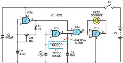
This circuit uses a single coil and nine components to make a particularly sensitive low-cost metal locator. It works on the principle of a beat frequency oscillator (BFO).
The circuit incorporates two oscillators, both operating at about 40kHz. The first, IC1a, is a standard CMOS oscillator with its frequency adjustable via VR1.
The frequency of the second, IC1b, is highly dependent on the inductance of coil L1, so that its frequency shifts in the presence of metal. L1 is 70 turns of 0.315mm enamelled copper wire wound on a 120mm diameter former. The Faraday shield is made of aluminum foil, which is wound around all but about 10mm of the coil and connected to pin 4 of IC1b.
The two oscillator signals are mixed through IC1c, to create a beat note. IC1d and IC1c drive the piezo sounder in push-pull fashion, thereby boosting the output.
Unlike many other metal locators of its kind, this locator is particularly easy to tune. Around the midpoint setting of VR1, there will be a loud beat frequency with a null point in the middle. The locator needs to be tuned to a low frequency beat note to one or the other side of this null point.
Depending on which side is chosen, it will be sensitive to either ferrous or non-ferrous metals. Besides detecting objects under the ground, the circuit could serve well as a pipe locator.
Gold Detector
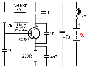
This very simple circuit will detect gold or metal or coins at a distance of approx 20cm - depending on the size of the object.
The circuit oscillates at approx 140kHz and a harmonic of this frequency is detected by an AM radio.
Simply tune the radio until a squeal is detected.
When the search coil is placed near a metal object, the frequency of the circuit will change and this will be heard from the speaker.
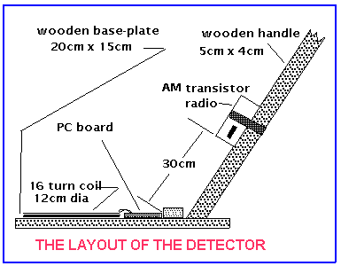
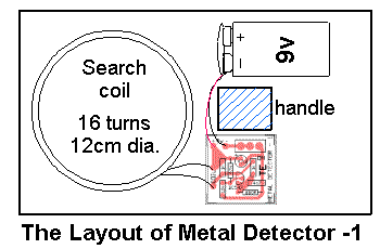
The layout of the circuit is shown and the placement of the radio.
The TRUTH about Metal (GOLD) Detectors.
A Gold Detectors club in the US created a challenge with 12 members with skills ranging from 12 months detection to over 25 years. They used 5 different detectors to find 30 different items, hidden in sand and under pieces of cardboard.
The results were these: All detectors performed almost equally but the interpretation of the beeps, sounds and readings on the detector were
quite often mis-read and the winner was a member with 1 year experience.
The moral of the story is to dig for anything that is detected as it may not be a "ring-pull."
With these findings you can clearly use a very simple, cheap, detector and get results equal to the most expensive equipment.
The only thing you have to remember is this: You need the right frequency for the type of soil to cancel out the effects of minerals etc.
That's why there is a range of frequencies from 6kHz to 150Hz.
All the other modes of producing and injecting the pulse add only a very small improvement to the detection process.
The energy put into the injecting pulse also has an influence of the depth of detection.
Cable Tracer
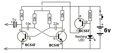
The transmitter is built on a small length of PC board, cut into lands with a file. The photo clearly shows how all the components are mounted and how the board is fitted into a toothbrush holder. The flashing LED shows the unit is ON and serves to control the beep-beep-beep of the circuit. The flashing LED is not an ordinary LED.
You cannot use an ordinary LED. It must be a FLASHING LED as this type of LED has a built-in resistor and a chip to make the LED flash.
The circuit does not make the LED flash, the LED makes the circuit beep-beep-beep due to the on-off from the chip inside the LED.One constructor used an ordinary LED - and BANG! That's why we are the first in the world to create a symbol for a flashing LED. The extra bar represents the chip inside the LED.
Transmitter Circuit
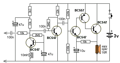
Receiver Circuit
The receiver circuit is a high-gain amplifier and produces constant background noise so the slightest magnetic field can be detected.
The 10mH choke can be any value but the largest number of turns on the core is best.
The mini speaker can be a 16R earpiece but these are not as loud as a mini speaker.
Quiescent current is 50mA so the on-off switch can be a push-button.
The 10mH choke can be any value but the largest number of turns on the core is best.
The mini speaker can be a 16R earpiece but these are not as loud as a mini speaker.
Quiescent current is 50mA so the on-off switch can be a push-button.
CABLE TRACER
Why pay $100 for a cable tracer when you can build one for less than $10.00! This type of tracer is used by telephone technicians, electricians and anyone laying, replacing or wiring anything, using long cables, such as intercoms, television or security.
Our cable tracer consists of two units. One unit has a multivibrator with an output of 4v p-p at approx 5kHz. This is called the transmitter. The other unit is a very sensitive amplifier with capacitive input for detecting the tone from the transmitter and a magnetic pickup for detecting magnetic lines of force from power cables carrying 240v. This is called the receiver. The circuit also has an inductive loop, made up of a length of wire, to pick up stray signals from power cables, so if one detector does not detect the signal, the other will. Our circuit is nothing like that in the professional unit shown above.
Sunday, June 26, 2011
Build your own PCB at home
source : http://blog.cytron.com.my/

I'm pretty sure there are lots of articles online which provides step-by-step solution on hand wash PCB. Nevertheless, it does not stop me from making the effort to write another similar article. However, this article is mainly aimed for those who are novice in this area. So, let's get our engines heated up~~!!
First and foremost, the materials.
1. PCB board

- PCB Board
2. Laser Printer connected to Computer
3. Glossy Photo Paper

- Glossy Photo Paper
4. Sand Paper (grit size 800 and above)

- Sand Paper
5. Ferric Chloride (FeCl3) (liquid or solid)

- FeCl3 acid
6. Iron

- Iron
7. Empty Container and unused toothbrush

- Container
8. Rag

- Rag
9. Hand drill

- Hand drill
10. Tweezers

- Tweezers
11. Cellophane Tape

- Cellophane Tape
12. Marker Pen (Fine Tip)
13. Thinner
14. Watercolour Brush
15. Pen Knife
After getting these materials ready, we're ready to RUN~~
Step 1: Transferring the circuit layout from PC to PCB
Print out the circuit layout (mirror it if you want it to be printed on top layer).
Cut the PCB board in accordance to the circuit layout.
Use sand paper to remove any unwanted material on the PCB. Wash away the dirts and dry the board with a dry rag.

- Preliminary Stage
When these things are ready, carefully align the glossy paper to the PCB board (use cellophane tape to ensure it's aligned) and then iron the paper to the board. Please be extra cautious while ironing the layout to the board. Make sure the heat is evenly spread, use the tip of the iron for better result. Next, you shall be able to successfully transfer the layout onto your board as shown in the picture below:

- Step 1 completed

- Fill in Gaps
Step 2: Etching
When your board is ready, the next step is to remove the unwanted coppers. This is the part where every safety precaution must be taken because we'll be dealing with chemical, highly erosive chemical. To be on the safe side, get yourself equipped with safety glasses and gloves.
Back to our topic, etching, first, mix the acid (FeCl3) with water. The amount of acid which are to be mixed is in accordance to the size of your board. As for my board(6mm x 5mm), I've only used one tablespoon of acid. Next, dilute it in water. (Caution: Gasses and smokes will be produced as a byproduct of this reaction)

- Dilute Acid with Water
Next, put the PCB, printed with circuit into the container and shake it~~ Try your best to not have direct contact with the acid. Bring the container as far as possible from yourself.

- Etching
Your board can be considered done when all the unwanted coppers are removed. You can pick it up with the tweezers from time to time to check with the etching process.
Please take note: DO NOT dispose the acid into drain or toilet bowl. If you are a student, I would suggest you to keep the acid in a glass bottle and give it to PCB lab in your campus. Else, you'll have to send it to the specialized company to handle it.
The board can be considered fully etched when it is like this:

- Fully etched board
Step 3: Drilling the board
The final step in fabricating a PCB is to drill the holes for through-hole components as well as via's (if it's a double layer board). Basically, drilling is not that hard. No proper training is required, just make sure that you drill in the right hole, right angle and right timing. To be honest, since this is my first time drilling, i basically screwed up my board. But then again, practice makes perfect So, here is a view of the final board, with all the components soldered on it...

- Final Product
Basic PIC16F877A circuit
Source : http://www.e-shore.com.my/
To operate a microcontroller, you need some basic components to support it and the circuit we call it basic circuit. The components needed are very common and you can find them at any electronics store out there. Below, i will share the schematic of basic circuit to operate a PIC16F877A microcontroller.


To operate a microcontroller, you need some basic components to support it and the circuit we call it basic circuit. The components needed are very common and you can find them at any electronics store out there. Below, i will share the schematic of basic circuit to operate a PIC16F877A microcontroller.

What are those components for?
- IN4148 - is a Shockley diode to allow the microcontroller to be programmed by ICSP method
- SW - is a 2 pins push button to allow manually reset the microcontroller
- R1k - is a 1K 1/4 W resistor to pull high or enable the MCLR pin
- XTAL - is a crystal oscillator to generate clock to the microcontroller
- C - supporting parts for the crystal
- VCC - 5V supply
- GND - 0V
How can you get 5V supply if you have a battery which is 12V? Below is the voltage regulating circuit to regulate a voltage from 7V-20V to a stable 5V.

What are those components for?
- JP - is a 2 pins connector to connect to battery. pin1 is positive and pin2 is negative.
- S - is a slide switch to on/off the power
- IN4007 - is a Diode to prevent wrong polarity
- LM7805 - is a 5V voltage regulator
- C - are capacitors to stabilize the voltage supply
- D8 - is a 5V LED as power on/off indicator
- R1K - is a 1K 1/4W resistor to limit the current through the LED
Now, the basic circuit is complete but you can't see any result yet because there are no input and output to show the result. Next, i will show you a simple input circuit.

Push button input is a very simple and direct input. As in the circuit above, S1 (Push Button) is being pulled up by R1 (10KOhm Resistor) to Vcc. So, when the S1 is being released, the voltage will be Vcc (since it is being pulled up to Vcc), and when S1 is being pressed, the voltage will be 0V. This type of input is called active low input, where the output voltage is 0V or Logic 0 when it is active (button pressed). The function of the R2 is to protect the Digital Input Port at microcontroller, just in case the Digital Input Port is being configured as an output, and the R2 will limit the current from the Port.
What are those components for?
- R1 - is a 10K 1/4W resistor to pull high the input pin
- Digital Input Port - Any digital input pin from the microcontroller
- S1 - is a 2 pins push button for giving input
- C1 - is a capacitor to filter the noise from the push button
- R2 - protect the Digital Input Port
Lastly, i will show you a simple output circuit.

The output is a LED. What are those components for?
- port - any of the digital output from the microcontroller
- 330R - is a 330 ohm 1/4 W resistor to limit the current through the LED
- Ds - is a 5V LED as output indicator
High current motor control using relay
Source : http://www.e-shore.com.my/
(MOSFET + Relay to drive the motor)

Basically, the circuit is using relay (2 set of Relay for each Motor) to switch the direction of the motor and MOSFET (1 set of MOSFET for each Motor) to control the speed of the motor. I will divide the MOSFET + Relay circuit into 3 part for the description, hope that you can completely understand the schematic.

This part is basically about how microcontroller output ports drive Relays. I hope you understand about how a Relay operate or you can read more about Relay here. To control a Relay from microcontroller, you need to convert the digital output signal (normally 0V for logic 0 and 5V for logic 1) from microcontroller to the coil voltage of the Relay, in this case 12V. For your information the INPUT1 and INPUT2 pin should be connected to microcontroller.
When the INPUT1 is logic 1, which is 5V, the Q1 will be turned ON, which also means RELAY1 pin will be shorted to GND. What happen here is the K1 Relay will be turned ON. The K1 Relay coil, Port 1 is actually connected to 12V by default and now Port 2 is shorted to GND (due the Logic 1 output from INPUT1) which complete the circuit and turn ON the K1 Relay.
However if the INPUT1 is logic 0, which will turn OFF the Q1 transistor, and RELAY1 pin will no longer shorted to GND. This will break the K1 Relay coil circuit and the K1 Relay will be turned OFF.
The similar description goes for INPUT2, Q2 Transistor and K2 Relay, which is another set of Relay.

Looking at the Relay and Motor, try to focus on how the NC (Normally Close), COM (Common), and NO (Normally Open) is connected to the Motor terminal (labeled M1 and M2). M1 and M2 is basically connected to the COM of both relay, NC of both Relay is connected to 12V and NO of both Relay is connected to MOSFET, where it will be shorted to GND when the MOSFET is turned ON (this will be discuss on the next part).

Looking at the diagram above, when K1 is turned OFF and K2 is turned ON, terminal 1 of Motor is connected to 12V, and terminal 2 of Motor is connected to GND. Depend on your Motor, let say, if we apply +ve at terminal 1 and –ve at terminal 2, the direction of the Motor will be Clockwise. To make it Counter-Clockwise, all you have to do is turn ON K1 Relay and turn OFF K2 Relay.

Now, when K1 Relay is turned ON and K2 Relay is turned OFF, terminal 1 of the motor is connected to GND and terminal 2 to the 12V, which will make the motor Counter-Clockwise.
So, whichever Relay is turned ON, that side of Motor terminal will be connected to GND, and when Relay OFF, that side of Motor terminal will be connected to 12V. What will happen if you turn ON both side of Relay? The answer is simple, both terminal of Motor will be shorted to GND, and nothing will happen, the Motor is in OFF condition or BRAKE condition. The same thing happen if you turn OFF both side of Relay.

The circuitry above, is basically the MOSFET Driving Circuitry, that convert the PWM output from Microcontroller at logic 5V to Logic 12V. This MOSFET Driving Circuitry also invert the PWM signal from Microcontroller. In the other words, when the output from Microcontroller is 5V, the output of MOSFET Driving Circuitry will be 0V, and when the output from Microcontroller is 0V, the output of MOSFET Driving Circuitry will be 12V. Don’t worry about the inverted signal from Microcontroller, you can re-invert the PWM output from Microcontroller in your programming to make it right. For example, let 0% PWM for full speed, 50% PWM for medium speed and 100% PWM for zero speed. This can be easily done in your coding.
There is a reason that you need all those transistor and resistor simply to drive a MOSFET. For IRF-Z48 N MOSFET, you can actually connect the PWM output from microcontroller directly to the G of the MOSFET to drive it. It will function correctly, but this will cause the internal resistance of the MOSFET to be higher compare to driving it using 12V logic. For X-Combat, the motor require very high current (up to 40A), and if we drive it directly using Microcontroller PWM output, the MOSFET will be overheated and spoiled. Depend on your application, you can also duplicate the MOSFET circuitry and connect them in parallel to get higher current output. For X-Combat robot, we use 2 set of MOSFET for each Motor.
I would like to add in something about PWM, in case you are not sure about what is PWM. Wiki for PWM, click here. PWM is basically Pulses in certain frequency, that the Pulse Width is changing. Imagine this, let say, you can now control your Motor using a push button, if you press it, the Motor will run and if you release it the Motor will turned OFF. Try to keep pressing and releasing the button in some frequency, and you will notice that the Motor is running not at full speed, probably around half speed, and maybe not so smooth. Back to PWM, the Pulses in your PWM signal is actually similar to how you press the button, but the PWM signal is able to perform very smooth, constant and higher frequency, compare to your hand. The frequency is fast enough that you will get a very nice constant speed output from your Motor instead of turning ON and OFF motor respond when you do it with your hand (pressing the button). In PWM it is not only ON and OFF, but you can also control how long it ON and how long it OFF. In one Pulse cycle, if you turn it on for 50% of the whole cycle, you are actually giving 50% of speed to the motor, and you can give any percentage you want (depend on your PWM specification), from 0% speed to 100% speed.

Back to the big picture of the schematic, the task of the Relay is to control the direction of the Motor, by connecting Motor terminal to either 12V or the MOSFET Circuitry. When any terminal is being connected to the MOSFET Circuitry, it is not necessary that it is shorted to GND. The MOSFET circuitry will now connect that terminal to GND in some frequency and Pulse width controlled by the PWM output from Microcontroller. So, that’s how the Relays control the direction and the MOSFET control the Speed working together to control a Motor.

Wiki for Flyback Diode here. D1, D2, D4 and D5 is actually the “Flyback Diode” for the motor. Flyback Diode is a diode (Schottky type Diode) normally found in circuit that involve any inductance load, in our case here, the Motor. Motor is actually a high inductance load, that will produce a lot of electromagnetic noise that will effects our Microcontroller. Depending on your application, you will need high current Schottky Diode if you are using High Current Motor. In X-Combat we use Schottky Diode that support up to 16A.
The C1 is a Multilayer Capacitor 0.1uF to help in filter out noise.
You can see all the “big” wire soldering line for the connection in the circuit for X-Combat.

Connector is also important, that it support enough current for your application.

I hope you can understand all my explanation, and feel free to leave comment if you have any doubt.
(MOSFET + Relay to drive the motor)

Basically, the circuit is using relay (2 set of Relay for each Motor) to switch the direction of the motor and MOSFET (1 set of MOSFET for each Motor) to control the speed of the motor. I will divide the MOSFET + Relay circuit into 3 part for the description, hope that you can completely understand the schematic.
Part 1: Relay

This part is basically about how microcontroller output ports drive Relays. I hope you understand about how a Relay operate or you can read more about Relay here. To control a Relay from microcontroller, you need to convert the digital output signal (normally 0V for logic 0 and 5V for logic 1) from microcontroller to the coil voltage of the Relay, in this case 12V. For your information the INPUT1 and INPUT2 pin should be connected to microcontroller.
When the INPUT1 is logic 1, which is 5V, the Q1 will be turned ON, which also means RELAY1 pin will be shorted to GND. What happen here is the K1 Relay will be turned ON. The K1 Relay coil, Port 1 is actually connected to 12V by default and now Port 2 is shorted to GND (due the Logic 1 output from INPUT1) which complete the circuit and turn ON the K1 Relay.
However if the INPUT1 is logic 0, which will turn OFF the Q1 transistor, and RELAY1 pin will no longer shorted to GND. This will break the K1 Relay coil circuit and the K1 Relay will be turned OFF.
The similar description goes for INPUT2, Q2 Transistor and K2 Relay, which is another set of Relay.

Looking at the Relay and Motor, try to focus on how the NC (Normally Close), COM (Common), and NO (Normally Open) is connected to the Motor terminal (labeled M1 and M2). M1 and M2 is basically connected to the COM of both relay, NC of both Relay is connected to 12V and NO of both Relay is connected to MOSFET, where it will be shorted to GND when the MOSFET is turned ON (this will be discuss on the next part).

Looking at the diagram above, when K1 is turned OFF and K2 is turned ON, terminal 1 of Motor is connected to 12V, and terminal 2 of Motor is connected to GND. Depend on your Motor, let say, if we apply +ve at terminal 1 and –ve at terminal 2, the direction of the Motor will be Clockwise. To make it Counter-Clockwise, all you have to do is turn ON K1 Relay and turn OFF K2 Relay.

Now, when K1 Relay is turned ON and K2 Relay is turned OFF, terminal 1 of the motor is connected to GND and terminal 2 to the 12V, which will make the motor Counter-Clockwise.
So, whichever Relay is turned ON, that side of Motor terminal will be connected to GND, and when Relay OFF, that side of Motor terminal will be connected to 12V. What will happen if you turn ON both side of Relay? The answer is simple, both terminal of Motor will be shorted to GND, and nothing will happen, the Motor is in OFF condition or BRAKE condition. The same thing happen if you turn OFF both side of Relay.
Part 2: MOSFET
From the Part 1, you’ve already able to control the direction of the Motor or turn OFF/BRAKE the motor, now, this MOSFET part will let you control the Speed of the Motor. More information about MOSFET here.
The circuitry above, is basically the MOSFET Driving Circuitry, that convert the PWM output from Microcontroller at logic 5V to Logic 12V. This MOSFET Driving Circuitry also invert the PWM signal from Microcontroller. In the other words, when the output from Microcontroller is 5V, the output of MOSFET Driving Circuitry will be 0V, and when the output from Microcontroller is 0V, the output of MOSFET Driving Circuitry will be 12V. Don’t worry about the inverted signal from Microcontroller, you can re-invert the PWM output from Microcontroller in your programming to make it right. For example, let 0% PWM for full speed, 50% PWM for medium speed and 100% PWM for zero speed. This can be easily done in your coding.
There is a reason that you need all those transistor and resistor simply to drive a MOSFET. For IRF-Z48 N MOSFET, you can actually connect the PWM output from microcontroller directly to the G of the MOSFET to drive it. It will function correctly, but this will cause the internal resistance of the MOSFET to be higher compare to driving it using 12V logic. For X-Combat, the motor require very high current (up to 40A), and if we drive it directly using Microcontroller PWM output, the MOSFET will be overheated and spoiled. Depend on your application, you can also duplicate the MOSFET circuitry and connect them in parallel to get higher current output. For X-Combat robot, we use 2 set of MOSFET for each Motor.
I would like to add in something about PWM, in case you are not sure about what is PWM. Wiki for PWM, click here. PWM is basically Pulses in certain frequency, that the Pulse Width is changing. Imagine this, let say, you can now control your Motor using a push button, if you press it, the Motor will run and if you release it the Motor will turned OFF. Try to keep pressing and releasing the button in some frequency, and you will notice that the Motor is running not at full speed, probably around half speed, and maybe not so smooth. Back to PWM, the Pulses in your PWM signal is actually similar to how you press the button, but the PWM signal is able to perform very smooth, constant and higher frequency, compare to your hand. The frequency is fast enough that you will get a very nice constant speed output from your Motor instead of turning ON and OFF motor respond when you do it with your hand (pressing the button). In PWM it is not only ON and OFF, but you can also control how long it ON and how long it OFF. In one Pulse cycle, if you turn it on for 50% of the whole cycle, you are actually giving 50% of speed to the motor, and you can give any percentage you want (depend on your PWM specification), from 0% speed to 100% speed.

Back to the big picture of the schematic, the task of the Relay is to control the direction of the Motor, by connecting Motor terminal to either 12V or the MOSFET Circuitry. When any terminal is being connected to the MOSFET Circuitry, it is not necessary that it is shorted to GND. The MOSFET circuitry will now connect that terminal to GND in some frequency and Pulse width controlled by the PWM output from Microcontroller. So, that’s how the Relays control the direction and the MOSFET control the Speed working together to control a Motor.
Part 3: Flyback Diode

Wiki for Flyback Diode here. D1, D2, D4 and D5 is actually the “Flyback Diode” for the motor. Flyback Diode is a diode (Schottky type Diode) normally found in circuit that involve any inductance load, in our case here, the Motor. Motor is actually a high inductance load, that will produce a lot of electromagnetic noise that will effects our Microcontroller. Depending on your application, you will need high current Schottky Diode if you are using High Current Motor. In X-Combat we use Schottky Diode that support up to 16A.
The C1 is a Multilayer Capacitor 0.1uF to help in filter out noise.
High Current Application
Another important point you have to remember in building High Current circuit is the connection wire use in the circuitry. You have to make sure that the connection, either soldering line, or wire or connector, from the battery terminal to the Motor must be enough to support the current required for the Motor.You can see all the “big” wire soldering line for the connection in the circuit for X-Combat.

Connector is also important, that it support enough current for your application.

I hope you can understand all my explanation, and feel free to leave comment if you have any doubt.
Subscribe to:
Comments (Atom)


